Installation - IO Wired Input
From VersaVision Support
Revision as of 15:39, 25 January 2024 by VVSupportAdmin (talk | contribs) (Created page with "<BR> <span style="box-shadow:2px 2px 15px #90A4AE; border-radius:5px; padding:20px">250px|link=Installation - IO Wired Input</span> <div style="text-align: center;"><span style="color:#0054a6; font-size:150%;"><u>'''OVERVIEW'''</u></span></div> <BR> The information below will explain how to connect an output from a Machine/Sensor into an Input on a Switch Contact Module. This would be used when the user wants to signal a fault on the machin...")

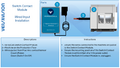
OVERVIEW
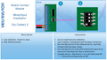
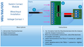
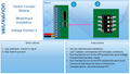
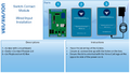
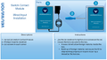
The information below will explain how to connect an output from a Machine/Sensor into an Input on a Switch Contact Module. This would be used when the user wants to signal a fault on the machine or record a count.
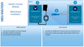
GENERAL
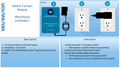
The Facilities or Maintenance Department will need to connect wiring to the Machine/Sensor and run the wires to the approximate IO Mounting location.
It is suggested that a hole be drilled into the IO Module to accommodate the wires OR the wires can also be brought into the box using the Cord Grip. This is the black connector at the bottom of the box where the power cord comes in.
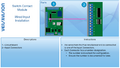
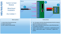
INSTRUCTIONS
1 of 10
2 of 10
3 of 10
4 of 10
5 of 10
6 of 10
7 of 10
8 of 10
9 of 10
1 of 10

|