I/O
From VersaVision Support
An I/O Expansion can be assigned to a PSM or Machine Interface Module. The setup of this Expansion will have Inputs and Outputs available.
The Inputs allow the user to configure a Wired Input from a machine or other external source. Inputs can be setup as Switches (On/Off), Counts (Pulse), or External Button (On/Off).
- Click Here for information on Contacts and how to Wire Inputs.
The Outputs allow the user to configure a Stack Light or Output for use as an Input on an external source.
An example of using the Output on and external source would be to trigger the Machines Kill Switch if a reason code has not been selected for a Machine Down Alert.
This page will provide information on the options available on an I/O Expansion Module.
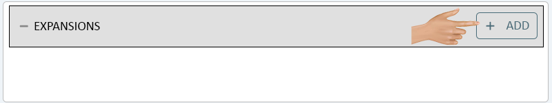
To access the I/O Expansion setup, the user will need to select the Add button in the Expansion section of the Configuration Properties.
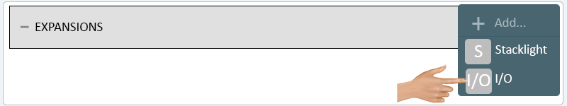
Select I/O from the pop-up Add Menu.
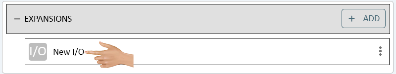
To access the I/O Properties, click on the New I/O section below the Expansions header.
INPUTS
General Settings Switch Count
 |
|
The I/O Properties will load on the right side of the Configuration Properties menu. Click in the Name field.
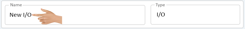
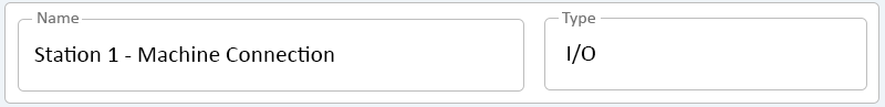
Enter a name for the I/O. The Type field is set to I/O, there are no other options available.
INPUTS
General Settings Switch Count
|
|
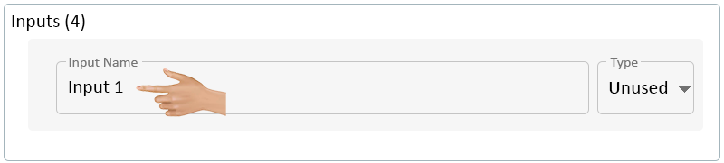
Below the I/O Name (General Settings), the Inputs section will be visible. By default, all of the Inputs will be set to "Unused". Click in the Input Name field.

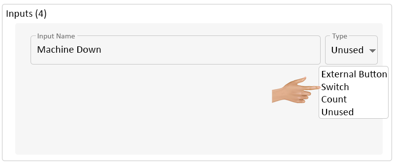
Enter a name for the Input (Contact) - click on the down arrow in the Type field.
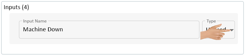
Select Switch or External Button from the drop down menu.
- NOTE: the External Button option is a Custom setup, please contact VersaCall Support for assistance.
Additional options will now show below the Input Name. Click in the On Delay field.
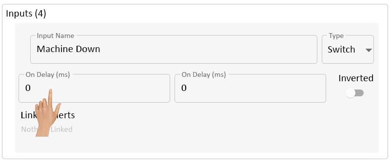
Use the On Delay if there is a need to delay the Alert activation.
An example of using this feature would be if the machine being monitored cycles for 10 seconds between parts. The user would want to set the On Delay to 11000 so that the Alert would not get Set until the machine had been down for at least 11 seconds.
Enter the correct amount of Delay needed for the Input being setup. Click in the Off Delay field. NOTE - times entered are in Milliseconds.
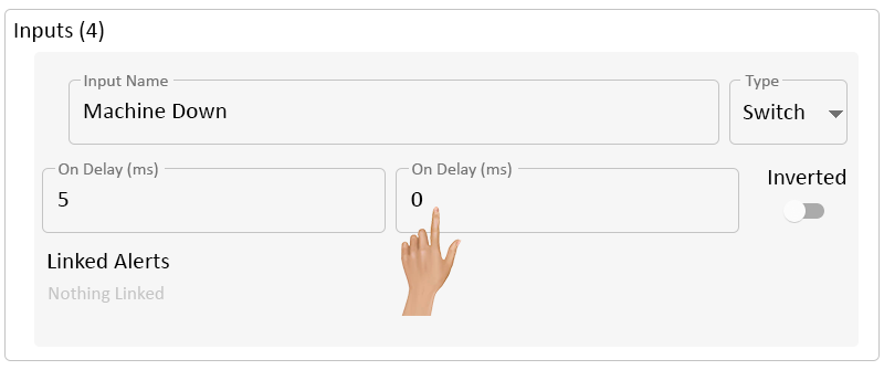
Use the Off Delay if there is a need to delay the deactivation of the Alert.
Enter the correct amount of Delay needed for the Input being setup. NOTE - times entered are in Milliseconds.
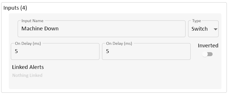
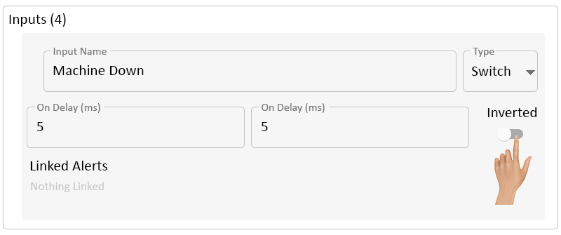
Toggle the Inverted switch to select to invert the Input signal. Select the best option for the Input being created
- Off - by default the Inverted switch will be OFF.
- The contact will Activate the Alert when the contact is On (completed circuit).
- On - Input will have the opposite behavior of Off.
- When contact is On, the Alert will NOT be Active. The Alert will only be Activated when the contact is Off (incomplete/broken circuit).
- Off - by default the Inverted switch will be OFF.
Click in the Linked Alerts section.
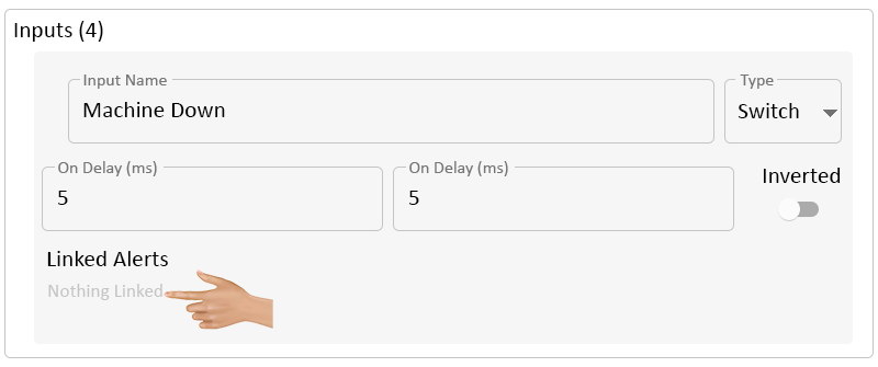
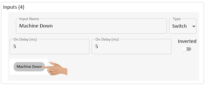
A pop-up menu will load with all of the Alerts that have been setup in the configuration. Select the Alert that should be controlled by the Input.
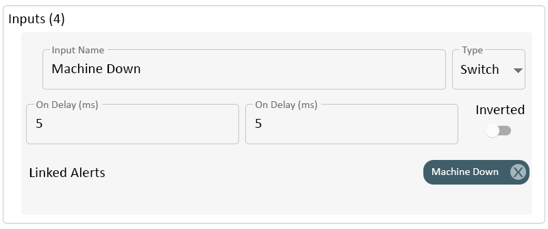
The selected Alert will show on the right side of the Linked Alerts section.
INPUTS
General Settings Switch Count
|
|
Below the I/O Name (General Settings), the Inputs section will be visible. By default, all of the Inputs will be set to "Unused". Click in the Input Name field.
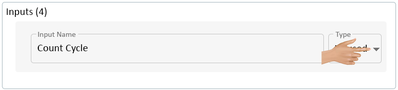
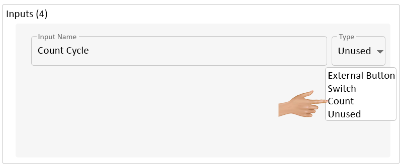
Enter a name for the Input (Count) - click on the down arrow in the Type field.
Select Count from the drop down menu.
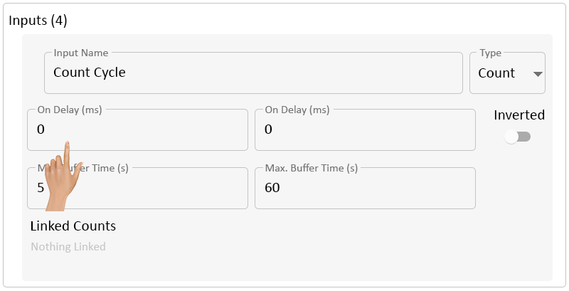
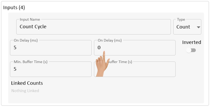
Additional options will now show below the Input Name. Click in the On Delay field.
Use the On Delay if there is a need to delay the Count activation.
Generally, this is used if the circuit has background noise.
Enter the correct amount of Delay needed for the Input being setup. Click in the Off Delay field. NOTE - times entered are in Milliseconds.
Use the Off Delay if there is a need to delay the deactivation of the Count.
Generally, this is used if the circuit has background noise.
Enter the correct amount of Delay needed for the Input being setup. NOTE - times entered are in Milliseconds.
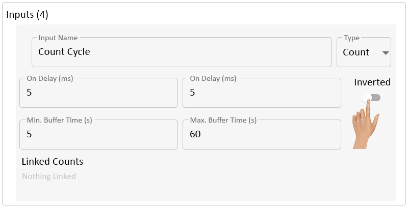
Toggle the Inverted switch to select to invert the Input signal. Select the best option for the Input being created.
- Off - by default the Inverted switch will be OFF.
- The contact will Activate the Count when the contact is On (Pulse).
- On - Input will have the opposite behavior of Off.
- When contact is On (Pulse), a Count will NOT be recorded. The Count will only be recorded when the contact is Off (End of the Pulse).
- Off - by default the Inverted switch will be OFF.
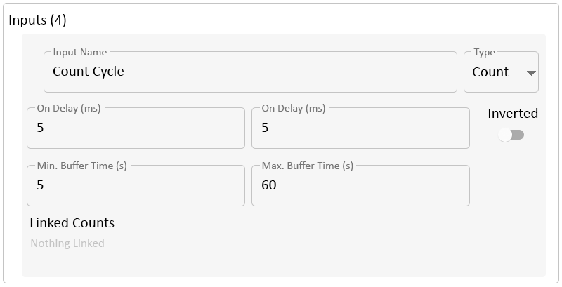
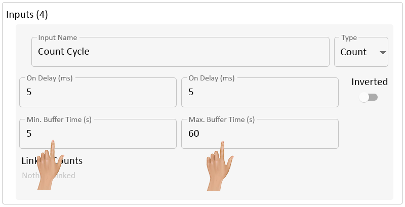
Below the Delay fields are Buffer Time fields, there are 2 fields available (Minimum & Maximum). Enter the best option for the Input being created.
- Min. Buffer Time (s) - when a Count/Pulse is received, the IO will wait at least (X) seconds before sending the Count Update to the system.
- If the IO receives another Count/Pulse within the (X) seconds, the IO will wait to send the Count Update.
- By default, the Minimum Buffer is set to 5 seconds.
- Max. Buffer Time (s) - the system will follow the Minimum time frame and hold the Count Update until the Max. Buffer has been exceeded.
- By default, the Maximum Buffer is set to 60 seconds. The IO will accumulate Counts for 1 minute before updating the system.
- Min. Buffer Time (s) - when a Count/Pulse is received, the IO will wait at least (X) seconds before sending the Count Update to the system.
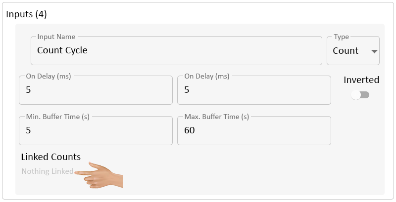
Click in the Linked Counts section.
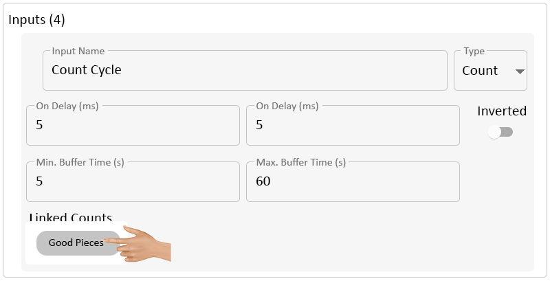
A pop-up menu will load with all of the Counts that have been setup in the configuration. Select the Count that should be controlled by the Input.
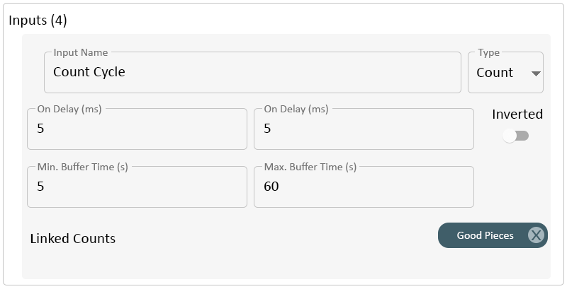
The selected Count will show on the right side of the Linked Counts section.
INPUTS
General Settings Switch Count
|
|
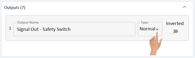
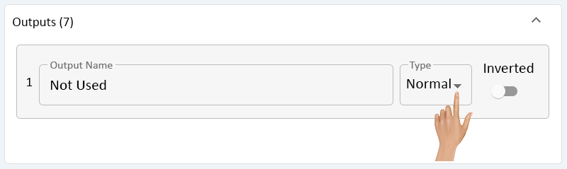
Below the Input Property section is the Output Property section. There is a total of 7 Outputs that can be configured.
Click in the Output Name field.
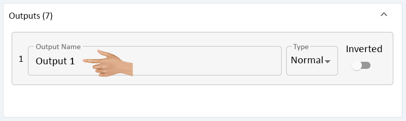
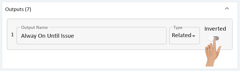
Enter a name for the Output. By default the Type field will be set to Normal.
A Normal Output means it will perform the Action (On, Off, Blink) that it receives.
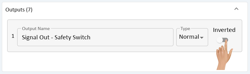
Toggle the Inverted option On or Off by toggling the switch.
- Off - the Output will perform the Action received.
- On - the Output will do the opposite of the Action received.
INPUTS
General Settings Switch Count
|
|
Below the Input Property section is the Output Property section. There is a total of 7 Outputs that can be configured.
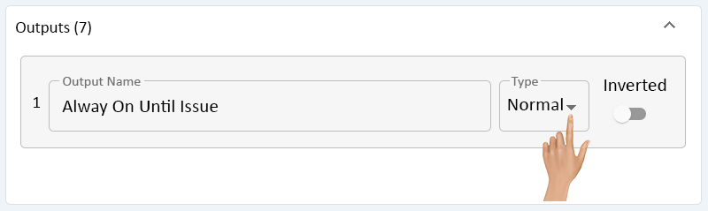
Click in the Output Name field.

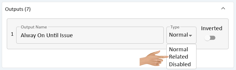
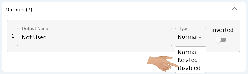
Enter a name for the Output. Click on the down arrow in the Type field.
Select Related from the drop down menu.
This allows the user to setup the Output to perform actions based on actions being performed by the other Outputs.
Toggle the Inverted switch to select to invert the Output signal. Select the best option for the Output being created.
- Off - by default the Inverted switch will be OFF.
- The Output will perform the Action received.
- On - the Output will perform the Opposite Action received.
- Off - by default the Inverted switch will be OFF.
A list of Outputs that can be selected for a Relation, will list out below the Output Name field. To select an Output, click in the box next to the name.
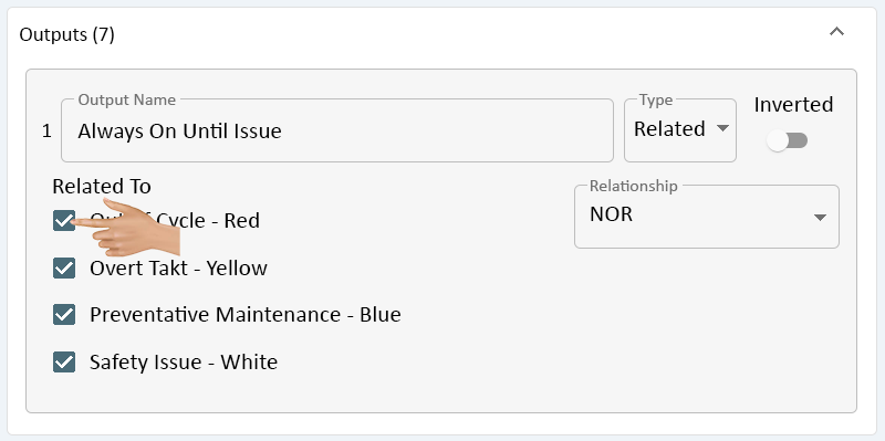
All selected Outputs will have a checkmark in the box. Click on the down arrow in the Relationship field.
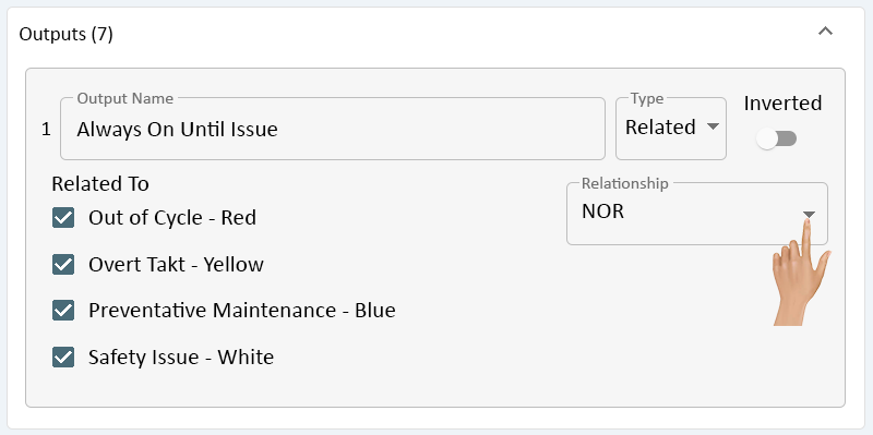
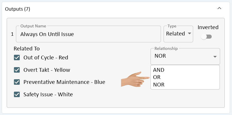
There will be 3 options available on the drop down menu - select the best option for the Output being created.
- AND - this setting allows the Output to functions when multiple Outputs are ON/OFF.
- An example would be to have the Output/Light turn on when the Red Light AND the Blue Light are OFF or ON.
- OR - this setting allows the Output to function when one OR more of the Outputs is ON/OFF.
- An example would be to have the Output/Light turn on when the Red Light OR the Blue light is OFF or ON.
- NOR - the setting allows the Output to do the opposite of other Outputs. This is generally the setting for the Green Light on a Stack Light.
- An example would be having the Green Light on a Stack Light on until another Light is activated. Once another is activated, the Green Light would turn OFF.
- AND - this setting allows the Output to functions when multiple Outputs are ON/OFF.
INPUTS
General Settings Switch Count
|
|
Below the Input Property section is the Output Property section. There is a total of 7 Outputs that can be configured.
Click in the Output Name field.

Enter a name for the Output. Click on the down arrow in the Type field.
Select Disabled from the drop down menu.
This Output will now be Off at all times and will not receive any signals. Good practice to set this option on the Outputs that are not being used.
INPUTS
General Settings Switch Count
|
|

|