Stacklight
From VersaVision Support

Any Module can be linked to 1 or more Stacklights. The Stacklight is an independent module that is controlled by the Module wirelessly.
In order to make the Stacklight connection, the user must add a Stacklight setup to the Module Configuration.
This page will explain the settings and options available when adding a Stacklight to a Module Configuration.
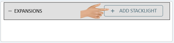
To add a Stacklight to a Module Configuration, the user will click on the Add Stacklight button on the Expansions section..
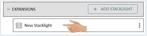
Under the Expansions section the user will see a New Stacklight marker. Click on the marker to view the Stacklight settings.
On the left side of the screen the user will see the Stacklight settings. At the top of the section there is a Name field, click in this field.
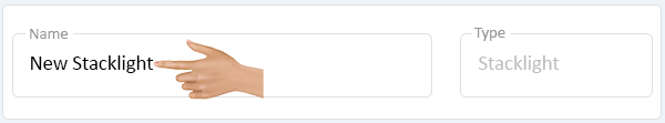
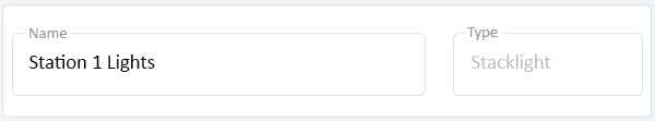
Enter a name for the Stacklight. The Type field will not be available for selection as this is a Stacklight.
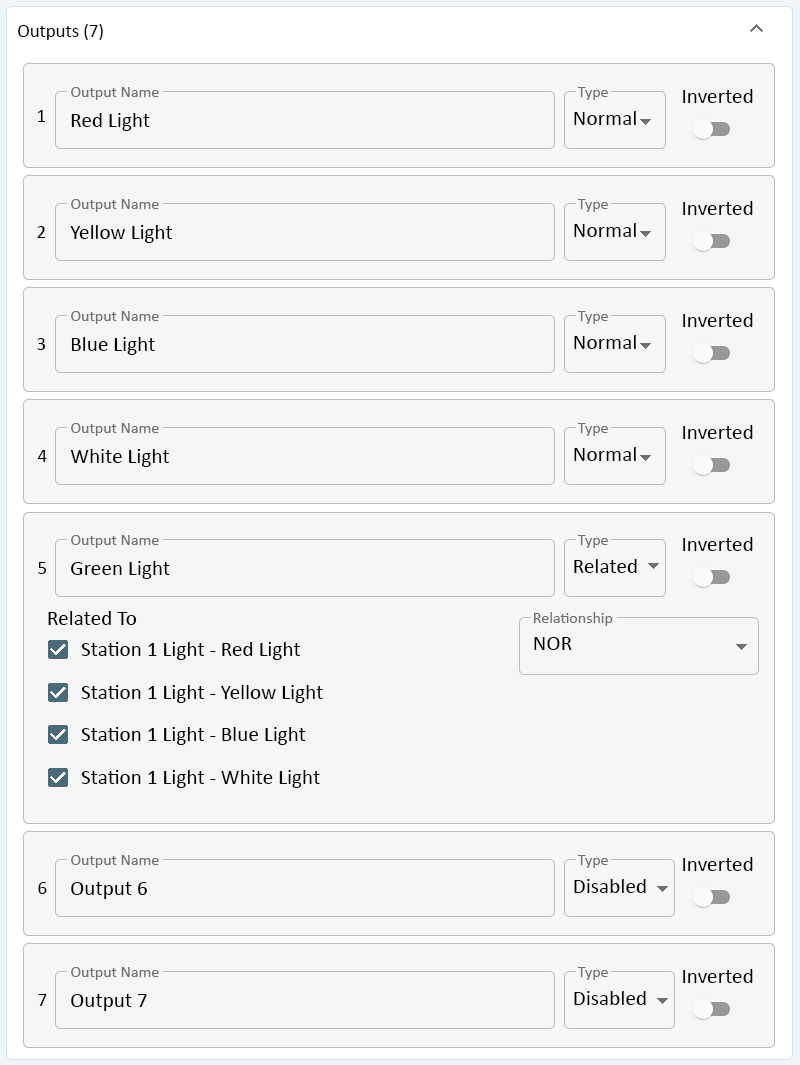
Below the Name & Type field are the Output settings/setup . By default, the settings will be filled out with the appropriate information.
- Output 1 - Red Light - these are the default settings for the Red Light attached to the Wireless Controls Module. This light is wired into the DO1 connector on the I/O Board by default.
- Output 2 - Yellow Light - these are the default settings for the Yellow Light attached to the Wireless Controls Module. This light is wired into the DO2 connector on the I/O Board by default.
- Output 3 - Blue Light - these are the default settings for the Blue Light attached to the Wireless Controls Module. This light is wired into the DO3 connector on the I/O Board by default.
- Output 4 - White Light - these are the default settings for the White Light attached to the Wireless Controls Module. This light is wired into the DO4 connector on the I/O Board by default.
- Output 5 - Green Light - these are the default settings for the Green Light attached to the Wireless Controls Module. This light is wired into the DO5 connector on the I/O Board by default.
- The Green Light is setup to act independently of the other lights, performing the opposite of each. The Green Light will be ON when all of the other lights are off. When on of the other lights turns on, the Green Light will turn off.
- Output 6 - this connector is not used on a Stack Light configuration.
- Output 7 - this connector is not used on a Stack Light configuration.
For users that need to setup a Standard Stack Light with Default functionality, nothing further is required. The user will need to setup Actions to make the Stack Light function based on a Monitoring Point State.
- Click Here for information on setting up actions.
Each Output on a Stack Light can be individually setup depending on the need. Click in the Output Name field.
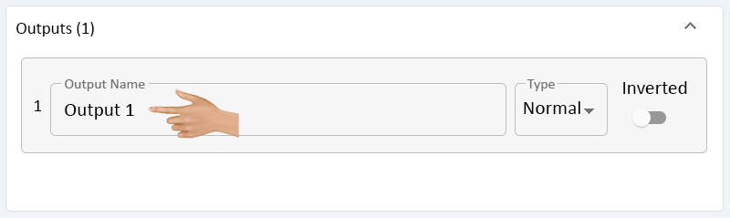
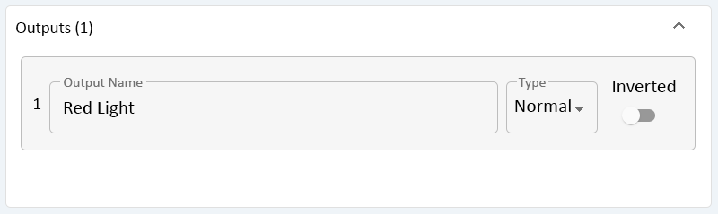
Type in the name that needs to be associated with the Output. For a Stack Light, this is generally the Color.
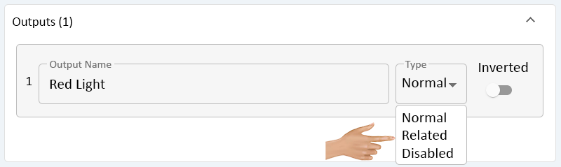
Click on the down arrow in the Type field.
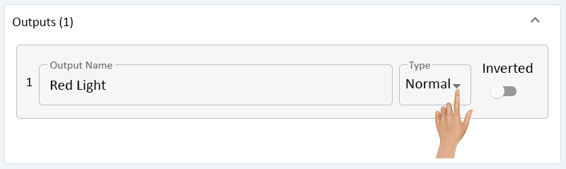
There will be 3 options available on the list. Select the best option for the Output being created.
- Normal - this setting allows the light to perform a normal function where Actions will instruct the Output to be On, Off or to Blink.
- Related - this setting allows the light to perform functions that are related to the other Outputs.
- An example is the Green Light being ON when the other lights are OFF and being OFF when none of the others are ON.
- Disabled - this setting disables the output so that it cannot be selected when setting up Actions.
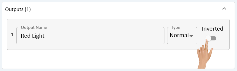
NORMAL
When the user selects the Normal Type, there is an Inverted setting available. Click on the toggle switch to enable this setting.
- Inverted - this allows the output to do the opposite of the signal.
- If an action turns the Output ON, the light will be OFF. If an action turns the Output OFF, the light will be ON.
- Inverted - this allows the output to do the opposite of the signal.
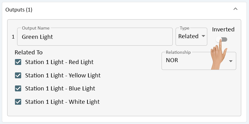
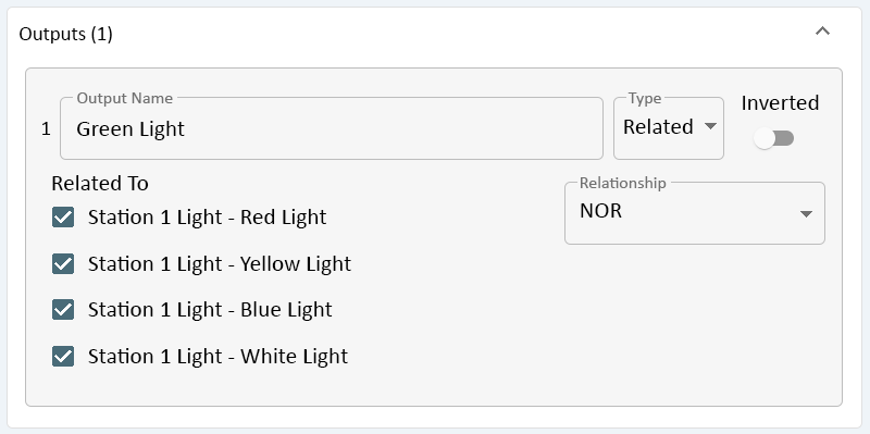
RELATED
When the user selects the Related Type, there is an Inverted setting available. Click on the toggle switch to enable this setting.
- Inverted - this allows the output to do the opposite of the signal.
- If an action turns the Output ON, the light will be OFF. If an action turns the Output OFF, the light will be ON.
- Inverted - this allows the output to do the opposite of the signal.
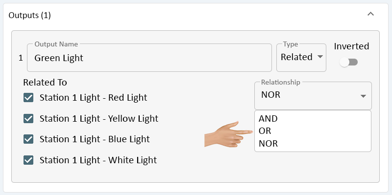
There is a Relationship field where the user can setup the functionality of the Output. Click on the down arrow in the Relationship field.
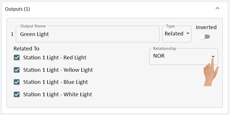
There will be 3 options available from the list. Select the best option for the Output being created.
- AND - this setting allows the Output to functions when multiple Outputs are ON/OFF.
- An example would be to have the Output/Light turn on when the Red Light AND the Blue Light are OFF or ON.
- OR - this setting allows the Output to function when one OR more of the Outputs is ON/OFF.
- An example would be to have the Output/Light turn on when the Red Light OR the Blue light is OFF or ON.
- NOR - the setting allows the Output to do the opposite of other Outputs. This is generally the setting for the Green Light on a Stack Light.
- AND - this setting allows the Output to functions when multiple Outputs are ON/OFF.
To the left of the Relationship field, the user will see a checklist of all Outputs setup as "Normal". Click on the checkbox for the Outputs that need to be considered for the Relationship selected.
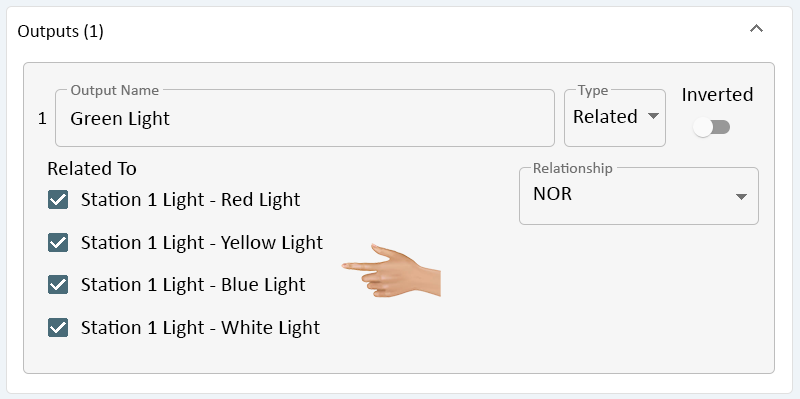
The example below shows the Green Light setup as a Normal relationship based on the state of all the lights.
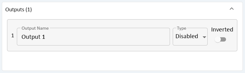
DISABLED
When the user selects the Disabled Type, the Inverted setting will be available. The Output will disregard any settings as it is Disabled/Turned Off.

|