Wired Outputs - Light Stack
From VersaVision Support
Outputs on an I/O Module or MIM can be used to connect to a Light Stack, Audio Device or any other Device that can accept a 24V signal.
This page explains where the Outputs & Relays are on the I/O and how to make the wired connections.
|
|
NOTE: Disconnect Power Before Accessing the Circuit Board.
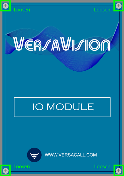
To access the Outputs on an I/O, the 4 screws on the lid must be loosened. The screws will not fully remove from the cover.

Remove the cover to expose the circuit board inside. The Output Connectors can be found at the top of the circuit board.
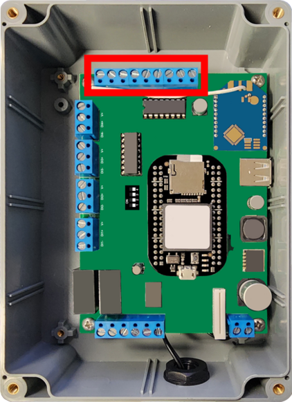
There are a total of 7 Outputs that can be setup.
There are 2 Relays attached to the Circuit board.
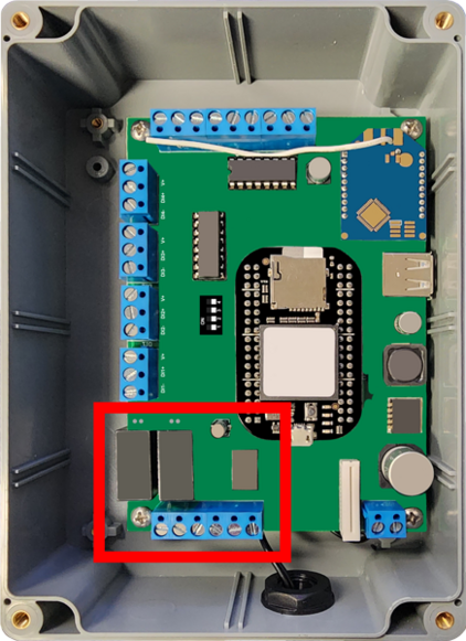
There is a Jumper connection for each Relay. A Jumper must be fitted to enable the Relay.
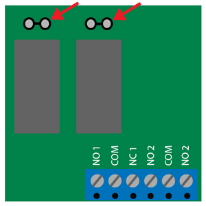
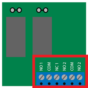
Each Relay has a connector. These are located below the Relay Switches.
|
|
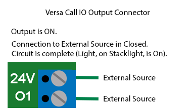
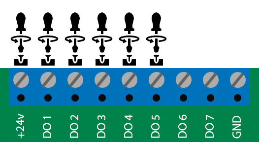
VersaCall uses an Open Collector on the Outputs of the board. The circuit get pulled to Ground when the Output is turned on.
Image below shows the circuit where the Output is OFF.

Image below shows the circuit where the Output is ON.
|
|
NOTE: Disconnect Power Before Wiring Outputs.
The instructions below explain how to wire a Stack Light into an IO Module. These instructions are based on VersaCall's standard wiring practice.
The Light Stack will have multiple wires with different colors. Image presented below is mapped out according to a VersaCall Provided Stack Light.
If the user has a Stack Light from a different source, please contact the supplier for the wiring information.
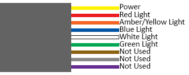
- Yellow - Power
- Red - Red Light
- Orange - Amber/Yellow Light
- Blue - Blue Light
- White - White Light
- Green - Green Light
- Brown - Not Used
- Grey - Not Used
- Purple - Not Used
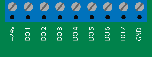
Each wire will need to be connected to the output bar at the top of the circuit board. To connect the wire, insert it into the hole on the front of the output bar and tighten the screw on top of the bar.
- WARNING - do not over tighten the screw as it can cause damage to the circuit board. Tighten until the screw stops turning no further.
Below is a diagram of where the wires need to be connected according to color and type.
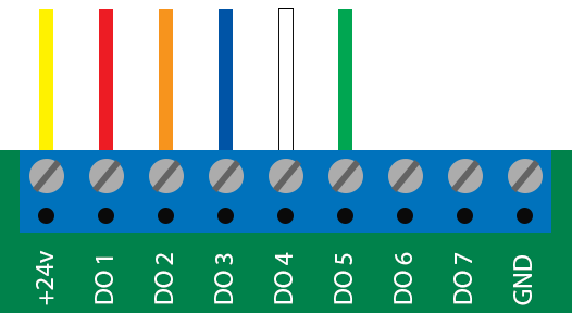
- Yellow - 24V
- Red - DO1
- Orange - DO2
- Blue - DO3
- White - DO4
- Green - DO5
- Brown - N/A
- Grey - N/A
- Purple - N/A
Place the cover back on to the IO module. Tighten down the 4 screws on the cover.
Mount the IO Module and plug in power.

- For Information on setting up the configuration for a Light Stack Click Here.
|
|
NOTE: Disconnect Power Before Wiring Outputs.
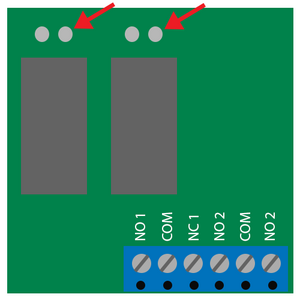
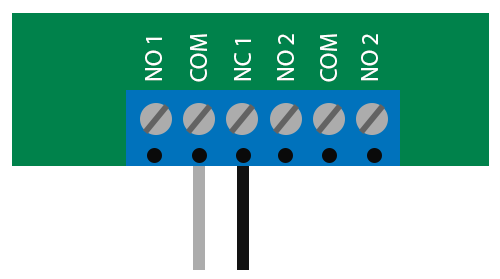
The VersaCall IO Module is supplied with built in Relays (SPDT Relay). These Relays are controlled by DO6 & DO7 (Outputs 6 & 7).
Each Relay has a Normally Open and Normally Closed option.
Image below shows how to wire a Normally Open output. Circuit is made when the Ouput is ON.
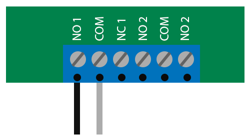
Image below shows how to wire a Normally Closed output. Circuit is made when the Output is OFF
|
|

|