Difference between revisions of "IT - Coordinator Requirements"
From VersaVision Support
| Line 3: | Line 3: | ||
<div style="text-align: center;"><span style="color:#0054a6; font-size:150%;"><u>'''OVERVIEW'''</u></span></div> | <div style="text-align: center;"><span style="color:#0054a6; font-size:150%;"><u>'''OVERVIEW'''</u></span></div> | ||
<BR> | <BR> | ||
The information provided below is intended for the IT Department. This will provide basic information they may need to setup a Coordinator when VersaCall Hardware has been purchased. | <div style="box-shadow:2px 2px 15px #90A4AE; border-radius:5px; padding:10px"> | ||
: | |||
:The information provided below is intended for the IT Department. This will provide basic information they may need to setup a Coordinator when VersaCall Hardware has been purchased. | |||
</div> | |||
<BR> | <BR> | ||
<div style="text-align: center;"><span style="color:#0054a6; font-size:150%;"><u>'''GENERAL'''</u></span></div> | <div style="text-align: center;"><span style="color:#0054a6; font-size:150%;"><u>'''GENERAL'''</u></span></div> | ||
<BR> | <BR> | ||
VersaCall Hardware communicates with the VersaVision Server using a 900mhz mesh signal. A Coordinator is required to receive signals from the individual modules and to send commands to those modules. | <div style="box-shadow:2px 2px 15px #90A4AE; border-radius:5px; padding:10px"> | ||
: | |||
:VersaCall Hardware communicates with the VersaVision Server using a 900mhz mesh signal. A Coordinator is required to receive signals from the individual modules and to send commands to those modules. | |||
:[[Mesh Network Specifications|'''CLICK HERE''']] for detailed information about the Mesh Signal/Network. | |||
</div> | |||
<BR> | |||
<div style="text-align: center;"><span style="color:#0054a6; font-size:150%;"><u>'''REQUIREMENTS'''</u></span></div> | <div style="text-align: center;"><span style="color:#0054a6; font-size:150%;"><u>'''REQUIREMENTS'''</u></span></div> | ||
<BR> | |||
<div style="box-shadow:2px 2px 15px #90A4AE; border-radius:5px; padding:10px"> | |||
: | : | ||
:<span style="color:#90A4AE; font-size:100%">'''USB Coordinator'''</span> | :<span style="color:#90A4AE; font-size:100%">'''USB Coordinator'''</span> | ||
| Line 23: | Line 30: | ||
::Pre-Installed Static IP Address (VersaCall) or DHCP Reserved IP Address based on the MAC Address of the Coordinator (Customer IT). | ::Pre-Installed Static IP Address (VersaCall) or DHCP Reserved IP Address based on the MAC Address of the Coordinator (Customer IT). | ||
::Outgoing Ports - [[IT - Ports#COOR|<u>'''Click Here'''</u>]] for information about Ports related to a Remote Coordinator. | ::Outgoing Ports - [[IT - Ports#COOR|<u>'''Click Here'''</u>]] for information about Ports related to a Remote Coordinator. | ||
</div> | |||
<BR> | |||
<div style="text-align: center;"><span style="color:#0054a6; font-size:150%;"><u>'''SPECIFICATIONS'''</u></span></div> | <div style="text-align: center;"><span style="color:#0054a6; font-size:150%;"><u>'''SPECIFICATIONS'''</u></span></div> | ||
::Dimensions – 3.5” (W) x 4.5” (L) x 1.5” (H) | <BR> | ||
<div style="box-shadow:2px 2px 15px #90A4AE; border-radius:5px; padding:10px"> | |||
: | |||
:Dimensions – 3.5” (W) x 4.5” (L) x 1.5” (H) | |||
:(1) 6’ Power Cord (included) - '''USB & Real-Port''' | |||
:(1) 6' USB Cord (included) - '''USB Only''' | |||
:(1) 6’ Ethernet Cord (included) - '''Real-Port Only''' | |||
:(1) 7” Antenna (included) - '''USB & Real-Port''' | |||
</div> | |||
<BR> | |||
<div style="text-align: center;"><span style="color:#0054a6; font-size:150%;"><u>'''DIAGRAM'''</u></span></div> | |||
<BR> | |||
<div style="box-shadow:2px 2px 15px #90A4AE; border-radius:5px; padding:10px"> | |||
<gallery mode="slideshow"> | <gallery mode="slideshow"> | ||
File:CoordinatorArch1.png|'''1 of 2'''|link=IT - Coordinator Requirements | File:CoordinatorArch1.png|'''1 of 2'''|link=IT - Coordinator Requirements | ||
File:MeshArch.png|'''2 of 2'''|link=IT - Coordinator Requirements | File:MeshArch.png|'''2 of 2'''|link=IT - Coordinator Requirements | ||
</gallery> | </gallery> | ||
</div> | |||
<BR> | |||
---- | ---- | ||
<div class="logo_img" > | <div class="logo_img" > | ||
| Line 42: | Line 60: | ||
|} | |} | ||
</div> | </div> | ||
<div class="logo_img" > | |||
{|style="background:transparent; color:black" border="0" height="100" align="right" valign="bottom" cellpadding=5px cellspacing=5px | {|style="background:transparent; color:black" border="0" height="100" align="right" valign="bottom" cellpadding=5px cellspacing=5px | ||
|+style="background:transparent| | |+style="background:transparent| | ||
| Line 48: | Line 67: | ||
|} | |} | ||
</div> | </div> | ||
<div class="logo_img" > | |||
{|style="background:transparent; color:black" border="0" height="100" align="right" valign="bottom" cellpadding=5px cellspacing=5px | {|style="background:transparent; color:black" border="0" height="100" align="right" valign="bottom" cellpadding=5px cellspacing=5px | ||
|+style="background:transparent| | |+style="background:transparent| | ||
Latest revision as of 16:29, 14 May 2024

OVERVIEW
- The information provided below is intended for the IT Department. This will provide basic information they may need to setup a Coordinator when VersaCall Hardware has been purchased.
GENERAL
- VersaCall Hardware communicates with the VersaVision Server using a 900mhz mesh signal. A Coordinator is required to receive signals from the individual modules and to send commands to those modules.
- CLICK HERE for detailed information about the Mesh Signal/Network.
REQUIREMENTS
- USB Coordinator
- 110v Power Outlet within 6 feet of placement/location.
- VersaCall Computer/Server within 6 feet of placement/location.
- Must be a Computer/Server Provided by VersaCall.
- Real-Port Coordinator
- 110v Power Outlet within 6 feet of placement/location.
- Ethernet Port within 6 feet of placement/location.
- Pre-Installed Static IP Address (VersaCall) or DHCP Reserved IP Address based on the MAC Address of the Coordinator (Customer IT).
- Outgoing Ports - Click Here for information about Ports related to a Remote Coordinator.
SPECIFICATIONS
- Dimensions – 3.5” (W) x 4.5” (L) x 1.5” (H)
- (1) 6’ Power Cord (included) - USB & Real-Port
- (1) 6' USB Cord (included) - USB Only
- (1) 6’ Ethernet Cord (included) - Real-Port Only
- (1) 7” Antenna (included) - USB & Real-Port
DIAGRAM
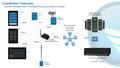
1 of 2
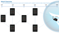
2 of 2
| USB Guides |
| Linux Guides |
| Red Hat Guides |
| Other Pages |

|